First, set the control on the circuit board to wide open. This increases the voltage to the solenoid valves coil and cause the current to increase. As a result, the magnetic field around the coil increases.
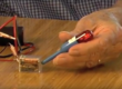
Place the Mag-Probe’s tip near the coil until the LED in the Mag-Probe lights.
Slowly move the Mag-Probe’s tip away from the coil until the LED turns off, then move then Mag-Probe’s tip toward the coil until the LED turns on now you’re at the outer edge of the magnetic field. Now we know that the coil is good.
The next step is to decrease the voltage to the coil by adjusting the control on the circuit board to the midpoint. This will cause the magnetic field to decrease causing the LED to go out. Now move the Mag-Probe toward the coil until the LED turns on. This should be the midpoint of the solenoid valves opening.
Then adjust the control on the circuit board to the off/close. The magnetic field should turn completely off and the LED will go out. Remember, the magnetic field should vary from large to medium and then zero as the control on the circuit board or from a remote location is switched. If the valves port does not follow the magnetic field as observed in the electrical tests, the problem is mechanical.
This procedure can be accomplished in 5 minutes or less once the sequence is learned.
Join Us On:
Facebook LinkedIn YouTube
If you have any technical questions please contact
Inventor Bob Bartol at (208) 866-7895
Email Bob at inventorbobis@gmail.com
[divider scroll_text=””]